Digital charging display mod

Toyota Rav4 EV Forum

Help Support Toyota Rav4 EV Forum:

This site may earn a commission from merchant affiliate links, including eBay, Amazon, and others.
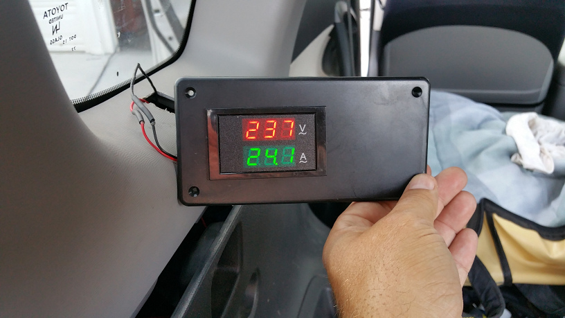
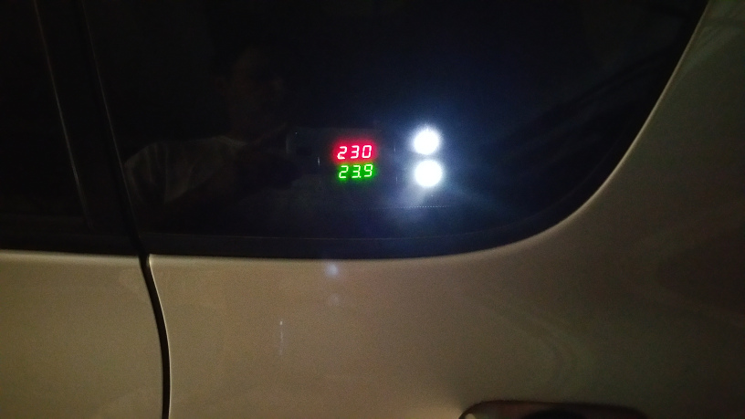
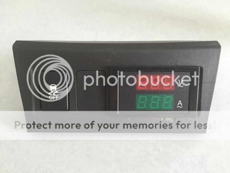
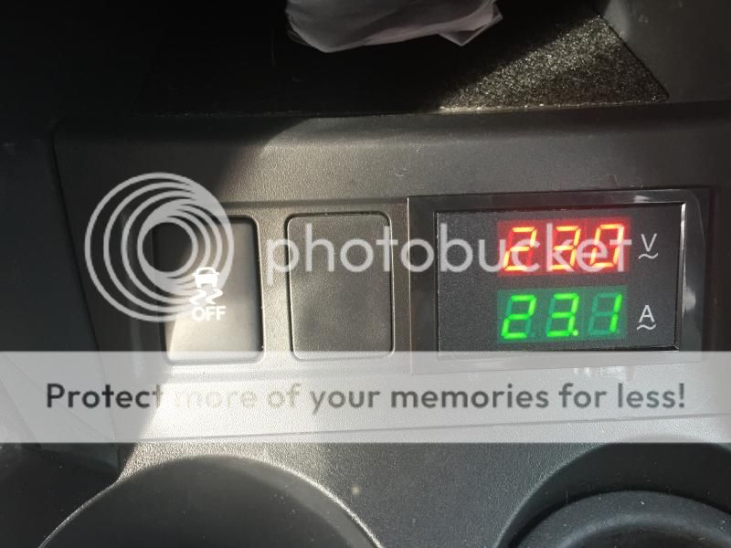
Jimbo - awesome pics and description. Thanks for the detail and step by step. I would also like to hear about reliability since the reviews on these chinese made displays are very mixed. It's interesting your first display quit even though rated for 240VAC. I like the functions much better than only volts / amps for the second display. I've only public charged 3 times, but it is obvious that the different stations have incredibly different power capacities and the voltage / amperage information is critical to knowing what you actually get. Sometimes I think it's worth a drive to a different station.

Dennis, Nice display on the JB. I have a new JB for the trial program - no display. I'm not sure what it is set at yet and after the trial I will likely try to add the LCD and volts / amps displays. I like the plexi cover. This is a good idea for making the mod's without permanent changes to the factory cover. Important for me since the JB may get swapped / replaced in the future. They are getting the unit safety certified and if changes are required they indicated my unit might be replaced with another after certification is complete.
 
dstjohn99, thanks for the feedback. I agree, the plexi cover modification makes it easy to restore a JB Basic back to its original "as shipped" condition. I'm hoping to get a second JB soon (for the same CPUC submetering trial as yours), so I can keep my existing JB in the trunk of my EVs for portable use only. I made a bunch of different types of AC adapters already for that specific purpose.

Btw, I just submitted a reply to your other post in another thread asking a few questions about the unit you just installed for the submetering trial.

I am also curious to know if the JB for the trial has the means to set the internal current limiter without taking off the cover plate, or is it just pre-set at the factory to 32A.
 
Dsinned said:
I am also curious to know if the JB for the trial has the means to set the internal current limiter without taking off the cover plate, or is it just pre-set at the factory to 32A.

No, still an internal pot for current adjustment. Info says the unit is shipped pre configured at either 30A or 50A operation as specified on my order, but I don't remember specifying (it's been a while). I haven't had time to confirm either with Entune emails down. I only used it once so far - I forgot to plug in last night.
 
Thanks for the info. Even with the optional 50A rated output cable, they should preset the adjustment pot to 40A (80% of 50A) to prevent the possibility of overloading the AC input cable, 14-50R outlet and infrastructure wiring. When charging a RAV4 EV, the car itself will automatically limit to 40A anyway, so not really of concern to us.
 
Thank you Jimbo, this is awesome. I hope you leave the reads you get on plugshare. Really helps to know where the 'hot' ones are.
 
My version.

First setup
display2.jpg


Than I decided to put the 2 LED's in the same box as well
Went to fry's and bought 2 x linrose superbrite led B4383H4-12Volt (white)

Placing of the radio shack box
display4.jpg

I put more protection where the cables are going through the metal and zip tied it thoroughly

During daylight
display3.jpg


at night
display1.jpg
 
Fromport: I like your setup that like Tony's has the meter in the back side window. I use public charging a lot now and my biggest frustration is not knowing what they're delivering.

Are the two white lights simply replacements for the 2 original ones? Meaning, do they exhibit the same blinking pattern as the originals? If so, I wonder if there is some way to convert that into either a basic SOC meter or "Time until full' reading. The RAV's touchscreen shows us that basic but horribly inaccurate information for charging at 120v and 240v, but doesn't know what wattage the car is actually charging at.
 
Larry_in_Seattle said:
Fromport: I like your setup that like Tony's has the meter in the back side window. I use public charging a lot now and my biggest frustration is not knowing what they're delivering.

Exactly why I installed this mod !

Are the two white lights simply replacements for the 2 original ones?
yes
I opened up the original Leds and found out there is a 750Ohm resistor in series, meaning it is setup for 12 Volts
original_rav4_led.jpg

So when I went to fry's, I found 12 Volt leds, simple 1:1 replacements.
link from other party:
http://www.calcentron.com/Pages/linrose/linrose_jumbo_led_panel_mount.html
Meaning, do they exhibit the same blinking pattern as the originals? If so, I wonder if there is some way to convert that into either a basic SOC meter or "Time until full' reading. The RAV's touchscreen shows us that basic but horribly inaccurate information for charging at 120v and 240v, but doesn't know what wattage the car is actually charging at.

Yeah that would need some digging into canbus messages and figure out what codes represent the current charge state and put that on a display. I will put that on my 'TODO' list ;-)
Next project I am currently working on is the override for entering data into the navigation while driving.
 
"Next project I am currently working on is the override for entering data into the navigation while driving."

Yes, yes, and YES on that one! We can mess with play lists, sound parameters, and a whole host of other things while driving, but not the NAV system. Drives me crazy.
 
UPDATE:

Thanks fromport for posting your version. Its a perfectly good option and I am sure many people will like it.

For me, as I said before, I charge publicly a lot and on long trips. I wanted a display I could see from inside the vehicle so I can glance at it while I am charging.

Its been extremely cold here in Ithaca NY for the past 4 months so I havent done anything with this until today. Today it got up to 22 degrees which is much warmer than the negative numbers we have had all month.

I had to swap out the current coil because the one for the blue display only showed half the voltage when used with the new display. I also moved the display back to the center console which is where I prefer it. Unfortunately my hands were shaking from the cold and I messed the bezel up a little but I have already ordered a new one. I may try it again when it warms up. I really hate this damn weather!

Here are some photos.

20150225_191950065_iOS_zpsrqrjkhjp.jpg


20150226_202744317_iOS_zpsugivlmat.jpg


20150226_202731727_iOS_zpso850ddhf.jpg


20150226_205017427_iOS_zps0mx2yuxb.jpg


I also went back and modified a few of my previous posts to include more info.
 
jimbo69ny said:
UPDATE:
For me, as I said before, I charge publicly a lot and on long trips. I wanted a display I could see from inside the vehicle so I can glance at it while I am charging.
And for that, your way is perfect.
I rather go and grab a cup of coffee or something.
I just want to know what voltage/amps I am charging to lookup how many miles/timeunit I am gaining.

Its been extremely cold here in Ithaca NY for the past 4 months so I havent done anything with this until today. Today it got up to 22 degrees which is much warmer than the negative numbers we have had all month.
[SNIP]
I already moved 2 bee swarm catches in the back of my rav4ev. (talk about mass transport) ;-)
Spring is here in southern california.

I also went back and modified a few of my previous posts to include more info.

thanks for the update!
 
Hey Jimbo, just want to post and say THANKS for sharing!

Always want to do this myself, and thanks for this great write-ups, with details and pictures! Without it, the safety inputs/comments from the members would not have been here for the community. This makes its easier for anyone else to start this project, knowing the details are here in one place!

+10
 
Nice setup! The only thing I would do different, (to be a bit more conservative), is use a dual AC Voltage/Current display unit with Blue/Blue, instead of Red/Green colored LEDs.
 
When you make a wiring transition on a non-signal circuit to a smaller gauge line, appropriate fusing must be installed at that point.

7A381018-FF0D-455F-B30A-364864B27EBF_zpsrvejulaw.jpg


Jim, without a separate fuse on each of your light-gauge blue and white wires, if either wire chafed to ground, it could turn incandescent, filling your cabin with smoke in seconds. Whatever overcurrent protection built into the J1772 circuit won't likely feel a thing as an extra 50A gets diverted to ground; one hopes there's a GFCI backing up the charger, but one doesn't design circuit modifications to rely upon external GFCI saving one's bacon.

Electrical tape to insulate a 240V connection in an automotive application is not a best practice, either. And, while poking a bare lead though a larger copper wire bundle to provide signal and modest power supply to the display works, you won't find any OEM products fastening leads that way.

I mean this to be constructive, but I have to say that the build method you used is scary to me.

I'm going to steal the good parts, though :)
 
I know. Its a risk I took. If you send me a link to a good automotive 240v fuse and fuse holder Ill consider adding it.

The wire could be compromised in a driver side collision however there wouldn't be power if I was moving. If someone smashed into my car, while it was parked, and charging, then there could be an issue. Otherwise the wire isn't live unless I am charging. I protected the wire when I ran it so I'm not worry about it chaffing.
 
OK, I'll have a first-pass at this.

Some considerations . . .

Automotive wiring has a couple of environmental challenges: heat, movement, and moisture. Heat shouldn't be a factor here. I live on the wet side of the Pacific NorthWet and corrosion is a serious concern in these parts.

These two fuses (the voltage monitor and power supply leads) are never supposed to blow or need to be serviced, therefore they can be installed & buried; serviceability is not a factor.

The fuses should be at the point that the wire gauge changes to smaller, so if a fuseholder is used, the input lead would have to be (I am assuming) 8 ga., which is only going to be available on a hefty-sized fuseholder.

I propose using leaded picofuses. Something along the lines of a Littlefuse 0242.100UAT1, 250V 100ma (0.1A). I'd want to see a datasheet on your meter to see the current draw (or inline my Fluke milliammeter and take a direct measurement) before committing to 100ma here; there are several ampere ratings available.
242_series_fuses_DSL.jpg


Building on your splice idea, I propose slitting the orange insulation lengthwise long enough to expose one strand of each cable and work with it. For me, this would probably be about 5/8". Trim one end of a picofuse shorter, fish it under the strand and up twice, then solder it.

Use 3M Scotchkote Electrical Coating FD to coat the work area, perhaps multiple coats. That will take care of the moisture issue. Then a double-wrap of 3M 33 electrical tape -- a very good general-purpose electrical tape -- which furnishes the mechanical stabilisation of the joint as well as chafing protection. I don't expect this bundle to move, but you have to plan for the unexpected when safety & reliability are concerns.

That takes care of the unfused side of the fuse, both mechanically & electrically.

The other end of each picofuse gets two layers of heat-shrink tubing. Prep the wire to the meter by slipping a section of heat-shrink tubing, std. grade, followed by a section of 3M Heat Shrink Medium-Wall Cable Sleeves, IMCSN-0400-48A: 12-6 AWG, 4 ft length: this stuff has a self-adhesive quality to the inside and is good to prevent ingress of water.

Solder the wire to the free end of the picofuse, slide the std. heat-shrink tubing in place and shrink, followed by the larger 3M medium-wall, which has a recovered (shunken) diameter of 0.15", which should be a pretty decent match to the OD of the picofuse with the first layer of tubing in place.

Coat both ends of the heat-shrink tubing with the Scotchkote again.

Repeat for the other meter wire.

I think this would be a reasonable hobbiest-level safety design. Of course, it's going to triple or quadruple the cost of the project, due to having to buy minimum quantity of the ScotchKote (15 oz. can?) and the 3M medium-wall tubing (4' length) but I don't see a lot of shortcuts. I encourage others to chime in with good ideas on this.
 
Back
Top