dfergenson
Member
- Joined
- Nov 11, 2020
- Messages
- 20
RAV4 EV charging issue case study for MyRAV4EV forum:
I’m writing to document my successful resolution of a RAV4 EV charging issue caused by a blown fuse in the onboard charger. There is substantial overlap between my issue and this thread (http://www.myrav4ev.com/forum/viewtopic.php?t=2463&sid=29a9bda734c0e413058ea12395f8a713) so I’m skipping over a lot of the details about the replacement. But I also want to see what the community thinks of an idea that I have. I think that I can prevent this issue in the future while also making it easier to mitigate. If you want to hear more about that, just skip to the bottom where I ask for peer review in solid capitals. And I want to express my appreciation for Alflash whose remote diagnostics and guidance saved me at least days and perhaps a week in making this repair. I’ll describe my interactions with him later but for now it’s enough to say that he’s an honest Ukrainian mechanic, not a malicious cyber criminal preying upon the RAV4 EV community.
In a nutshell, my EVSE kept trying to charge my car but kept stopping before it even started. I removed the onboard charger, replaced a blown fuse, reinstalled the charger, and it’s been charging ever since. It sounds easier than it is. The first time took me about 12 hours, the second time 8 hours since I screwed up the first time, and the third time about 5 hours since I have a friend with the same issue.
Anyway, here’s the case study:
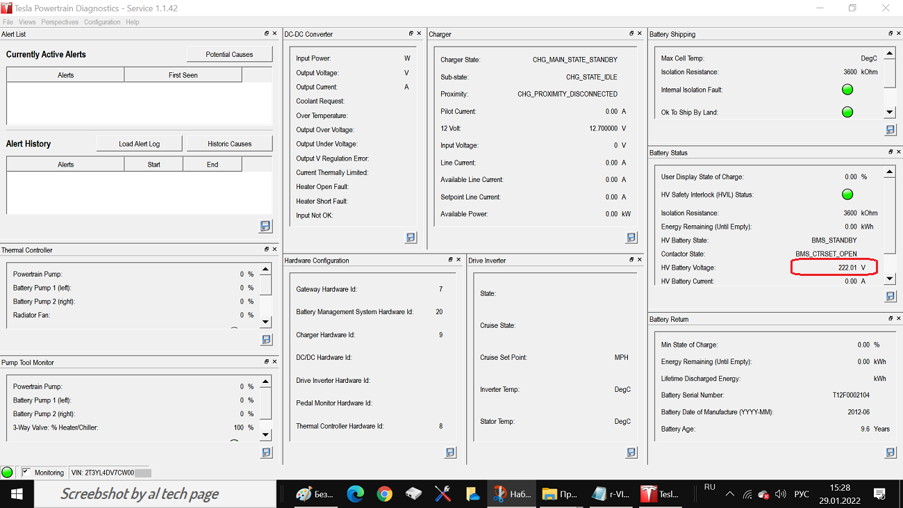
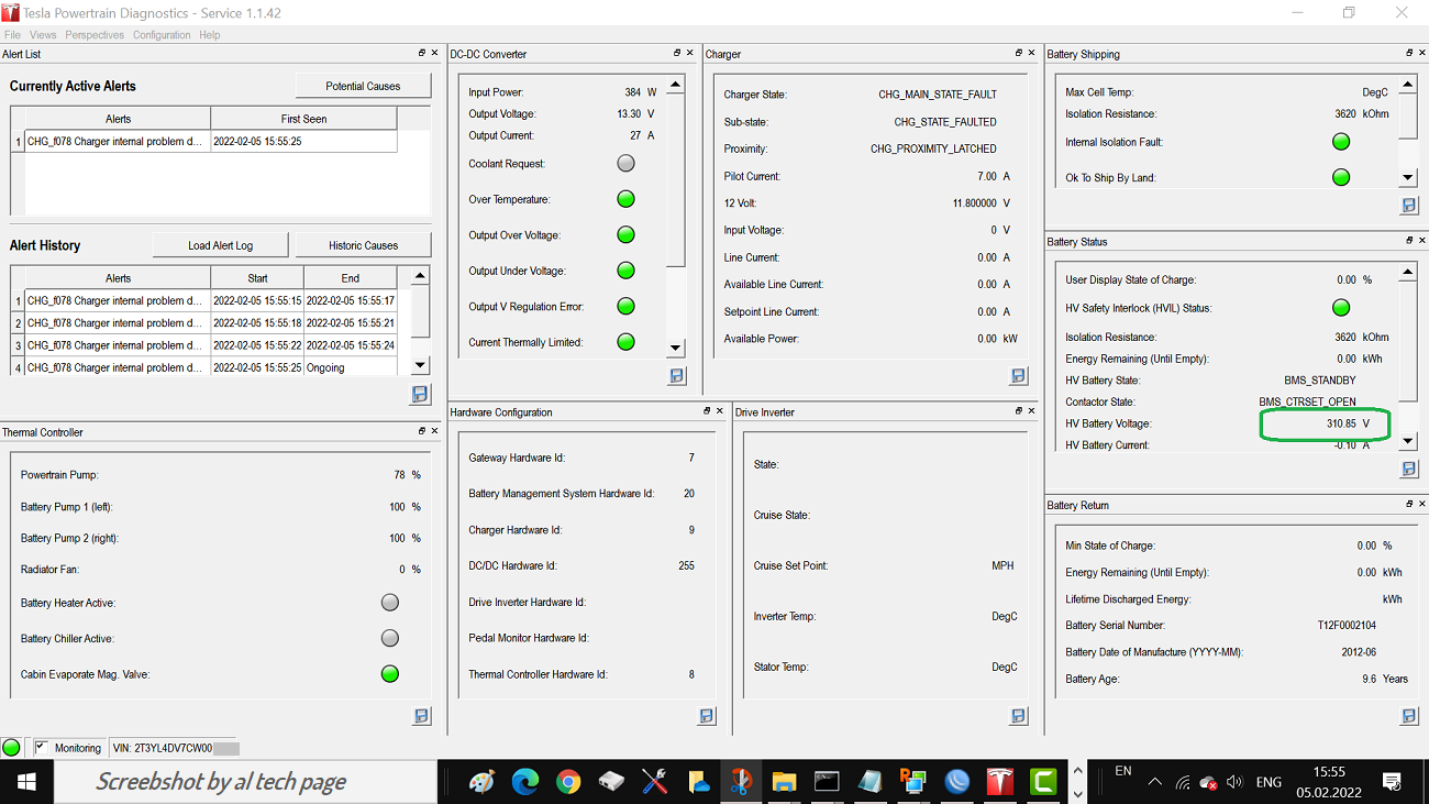
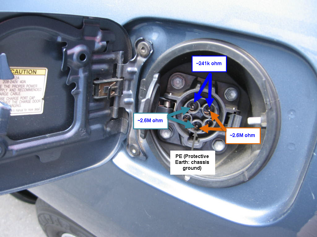
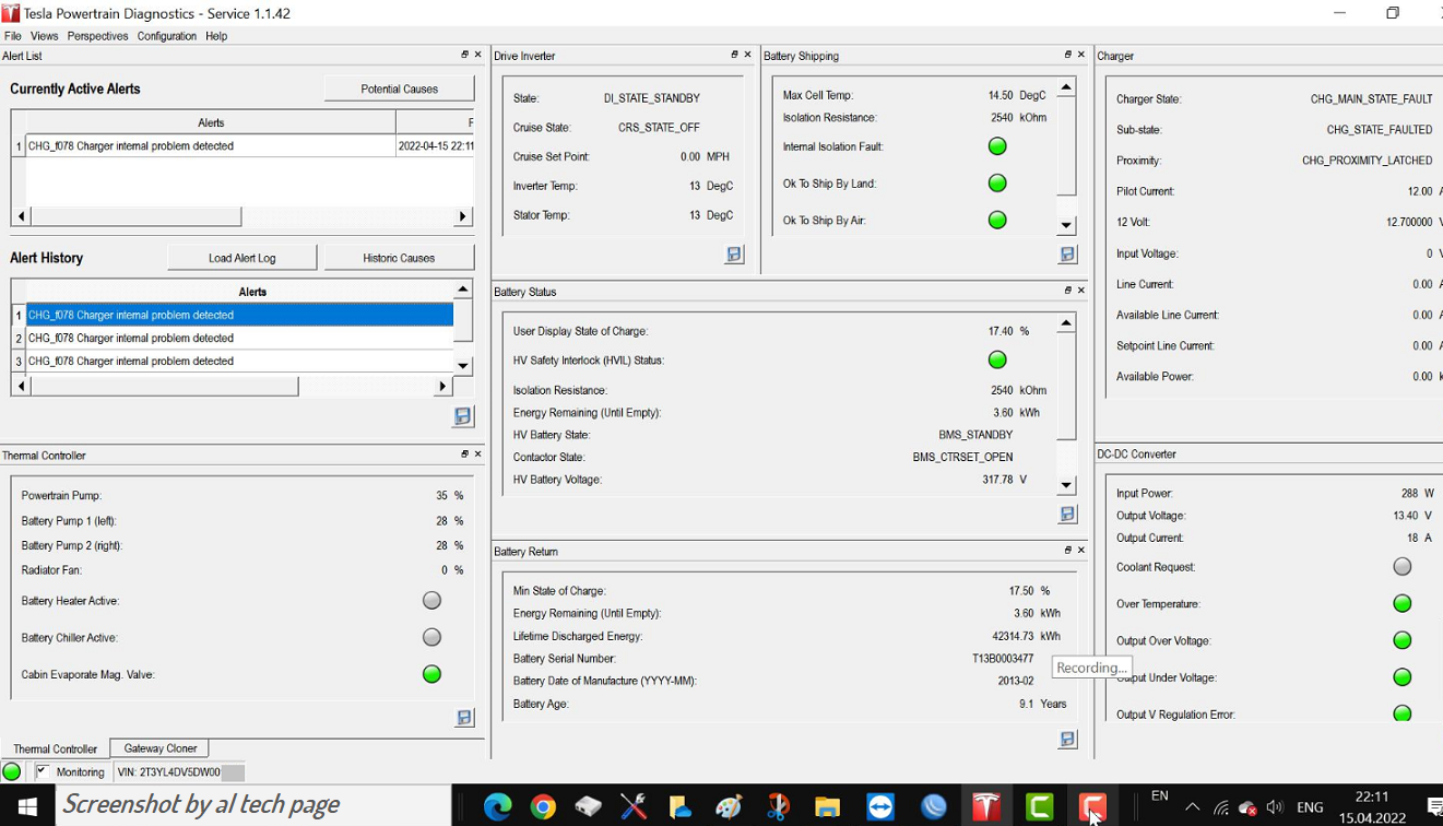
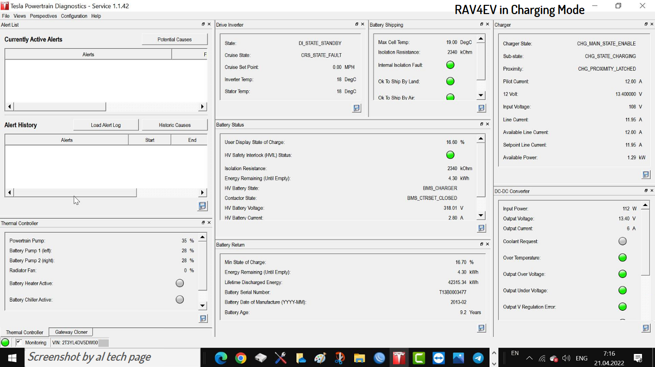
On April 9, 2022 I plugged my RAV4 EV into its Level 1 EVSE at my house and it failed to charge. The RAV4’s relays opened, then the EVSE’s relays opened, and then the EVSE’s relays closed again. The EVSE’s relays cycled through opening and closing three times before the RAV4 showed an error message and stopped attempting to charge. If I left it plugged in, it would attempt to charge from time to time and the same thing would happen. The same symptoms were observed on a different Level 1 EVSE and on a Level 2 EVSE. Replacing the 12V accessory battery did not improve the symptoms.
A YouTube video by Alflash shows two types of charging failures and mine was clearly Type 2.
https://youtube.com/watch?v=t29AjsbwXgo
The bottom lines is that there are fuses within the onboard charger that can go bad. Normally, fuses blow when there is a problem. In 90% of all cases that match these symptoms, the fuses ARE the problem. I’ll give my hypothesis as to why, along with a potential fix, later on. Regardless of the root cause, on RAV4 EVs and first generation Tesla Model S cars, the fix is the same most of the time: dig out the onboard charger and test the fuses. If one is blown, replace it and reinstall the charger. Most of the time, this clears the issue right up.
Removing and reinstalling the onboard charger is difficult. Alflash described it as “dragging a hippopotamus out of the swamp”. Good instructions are available from a few sources including Tech26’s thread where he posts a link to a Google images library. Online Chilton’s guides are no longer available to consumers but my local public library provides online access to Chilton’s professional manuals free of charge. Jfletter had a similar problem at about the same time and he came over and helped me with some of the more complicated parts of the removal. And, as I mentioned, Alflash was a great resource. One of the cable restraints was very difficult to remove but he walked me through the process. I describe that in the suggestions list below.
I’m going to assume that you will look at some of the other photographs, manuals and threads so I’m going to give some advice that may sound like gibberish but will make more sense when you encounter it in doing the job:
1. Drive the car up on ramps before you perform this repair. You will need the ground clearance. If your car is completely discharged, then jack it up using the front jack point and put it on jack stands.
2. Make sure you remove the battery service grip under the passenger seat before attempting any EV repair.
3. Remove the two panels under the car and drain both G48 coolant systems and the pink car heater system before you start. This will save much more time than it will take.
4. There’s no need to remove the cabin heat exchanger by itself. Just disconnect all of its connectors and remove its mounting bracket with it attached.
5. With two exceptions, the whole job can be done with only a 10 mm and a 12 mm socket but make sure that the 10 mm is of at least medium depth or it will bottom out on some of the nuts that are over studs and will strip those nuts. A universal joint for your ratchet will probably be necessary. So will a breaker bar and a few different lengths of socket extensions. A battery powered impact driver helped me a lot. I used 3/8” drive for everything because there were a lot of tool changes needed.
6. When you are removing the charger, first, disconnect the hose and the CAN bus connector from the driver’s side. Then, elevate the passenger side of the charger to provide visibility into the high voltage junction box that is attached to the outside of the charger. I used a cut off piece of 4x4 lumber to support it. Elevating it at an angle will cause G48 coolant to spill out of the charger so have a catch pan beneath the car when you do this.
7. Ignore the white plastic shroud on the outside of the junction box and the orange plastic box on the high voltage wires that run into the passenger compartment side of the junction box. Both of these are red herrings and you can remove the charger without disturbing them.
8. As best you can, note the routings of the hoses and cables before you remove any particular mount, hose or cable. Getting them all routed back is a lot like solving a Rubric’s Cube. Photos didn’t help me as much as I thought they would.
9. Most of the hose and cable clips can be released by pushing a screwdriver or needle nose pliers against the portion of the clip that protrudes from the opposite side of the mount that it attaches to. Then, it’s a matter of rocking that side of the clip up above the mount and repeating the same motion on the other side. If you can’t access the far side, you can force the bottom of clip up through its slot towards the one side that you did release. This is harder but the clip will remain functional.
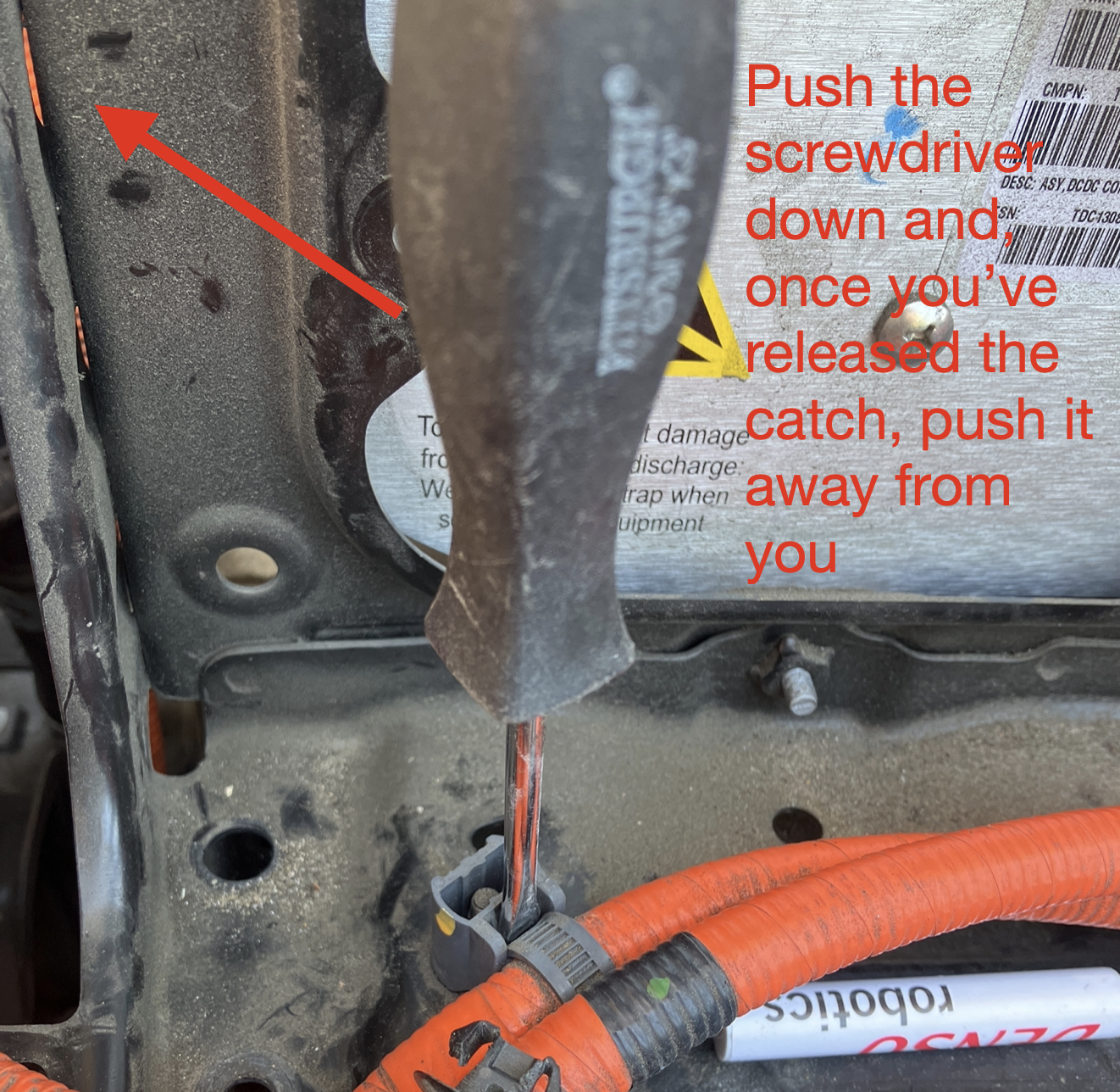
10. There is a grey clip with a hose restraint that zips in on the passenger side of the car. See photograph below. To release the strap, stick a flathead screwdriver down into the clip and then push away from you towards the passenger compartment. It will take a few of these operations to free the hose from the clip.
11. When you do the reinstallation, make sure to reconnect the CAN bus on the driver’s side of the unit. It’s towards the passenger compartment and the cable can easily fall down and out of sight. I missed this the first time and Alflash pinpointed this as the cause via remote diagnostics and sent me back to check the connection. When I found that I had forgotten to connect it, I felt like a very relieved idiot.
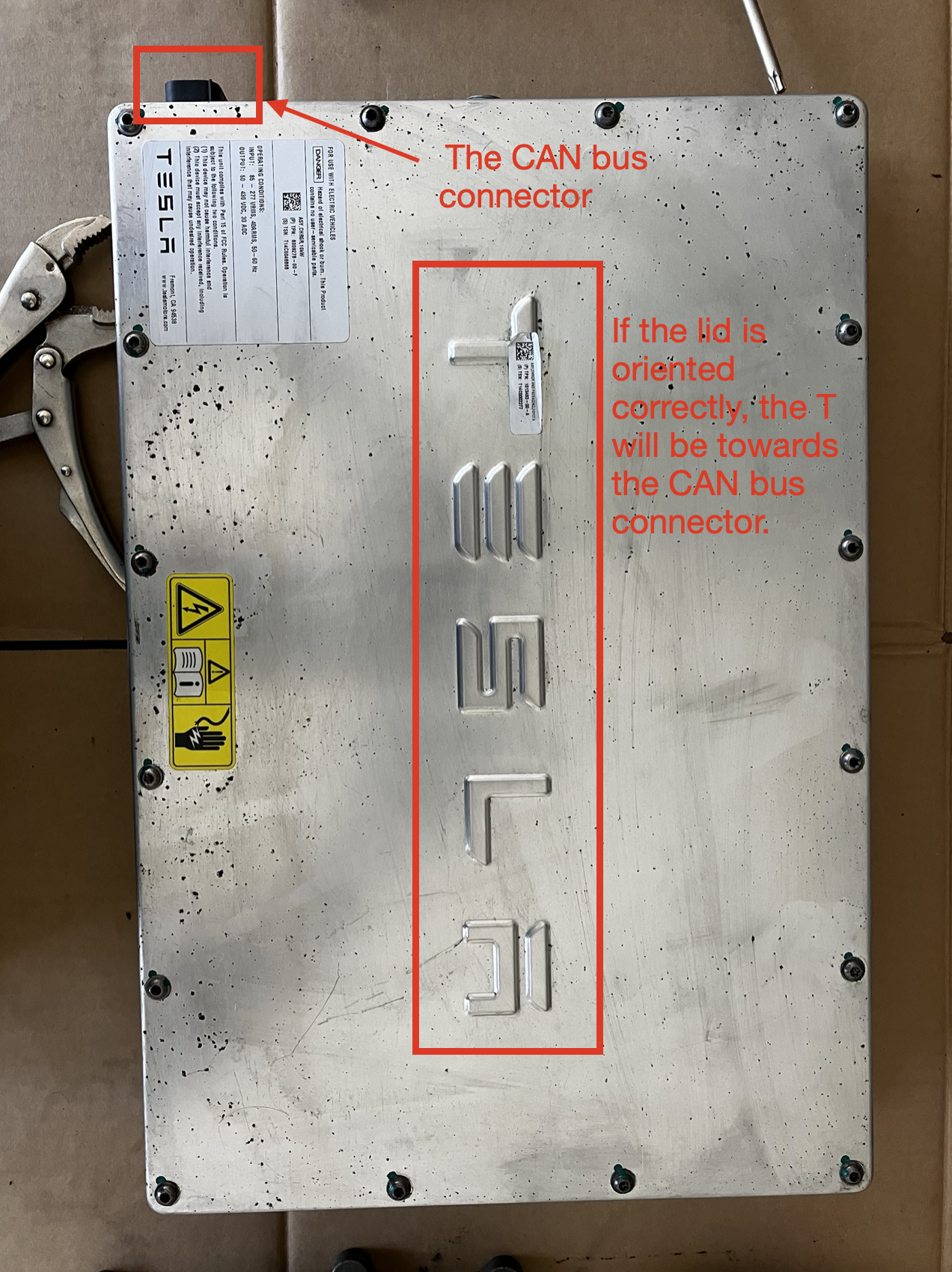
12. Note the direction of the case lid when you remove it so you don’t reinstall it backwards. It matters.
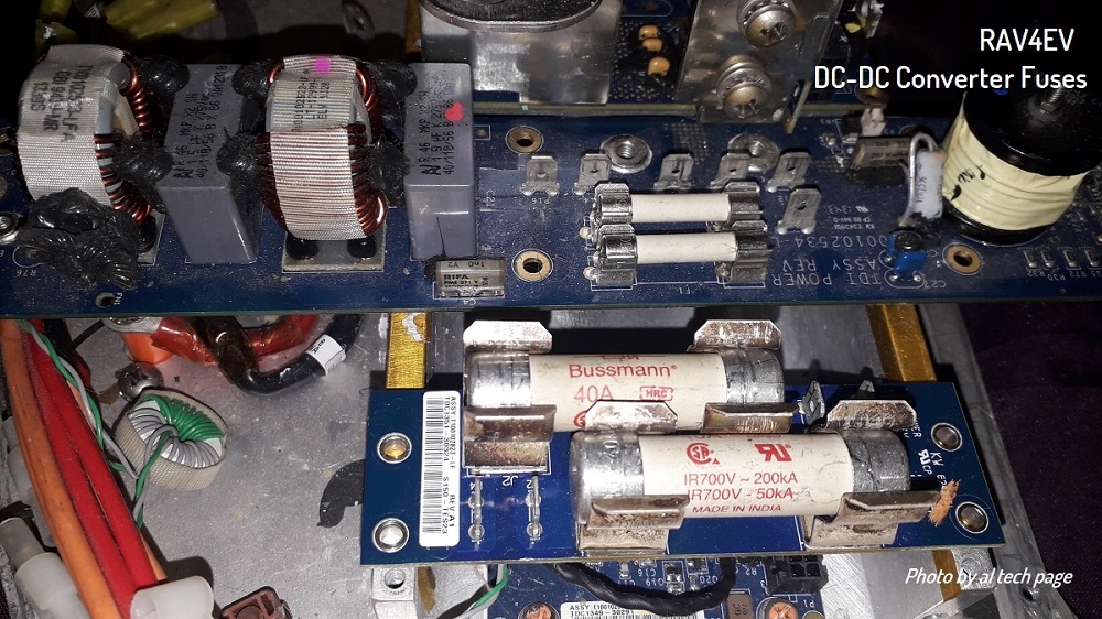
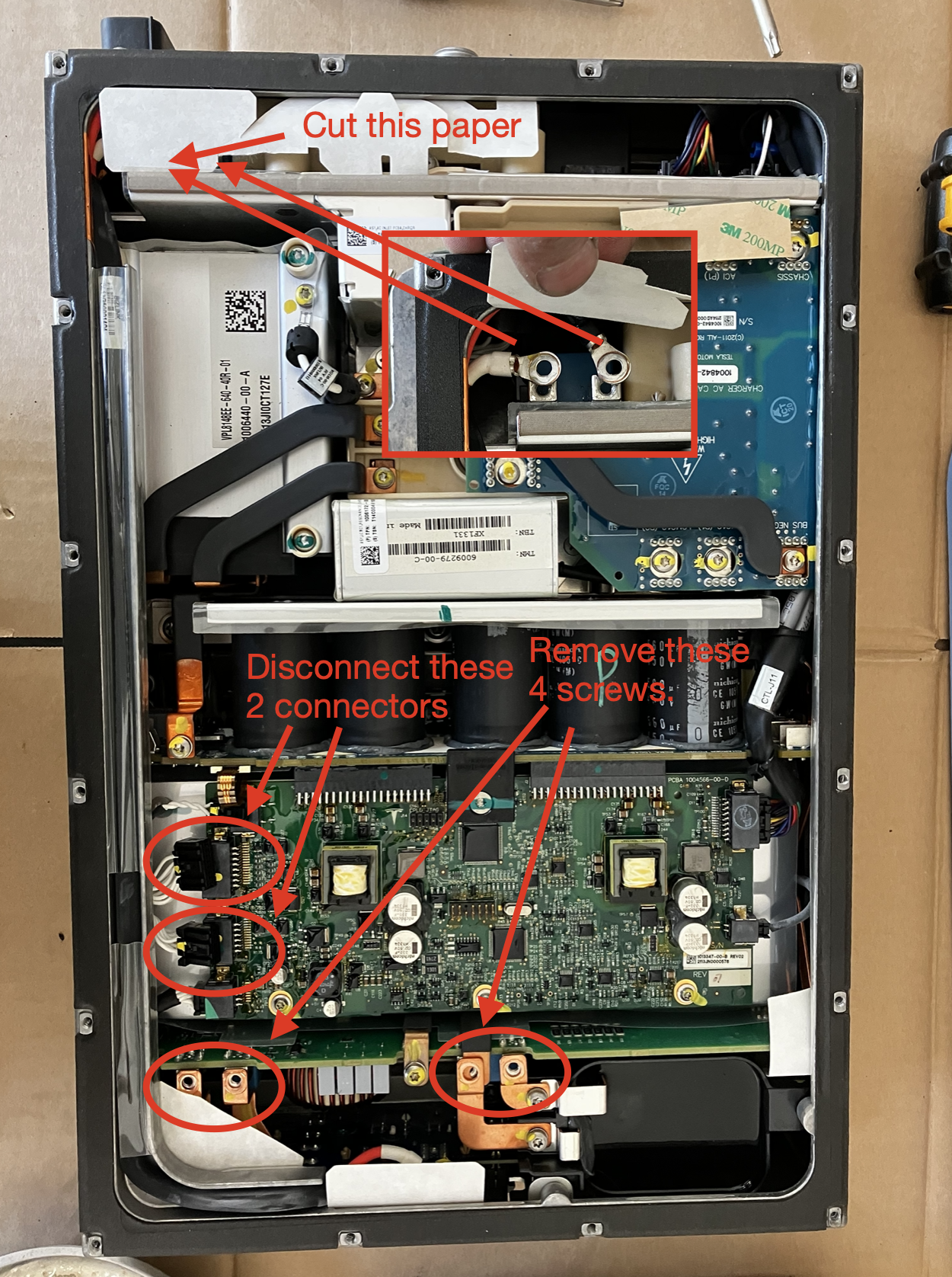
Once you have extracted the power supply, opening it up is fairly straightforward. There are three parts to the housing: the top, the walls and the base. All go together with the same torx screws. You need to take the top off, then disconnect a few things, and then take the walls off of the base to access the fuses.
I’ve posted a sequence of photos showing the process here:
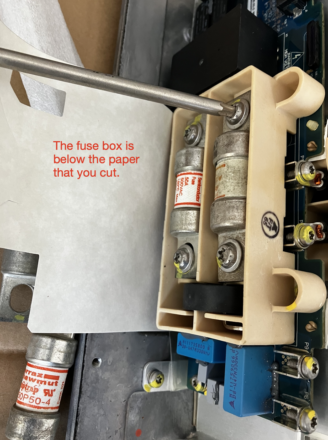
The fuses are Ferraz Shawmut Amptrap fuses, model A50P50-4, Form 101. There are a bunch of equivalents from other fuse manufacturers but be careful when you choose one because there’s something confusing in the specification: Form 101 does not refer to a form factor; it refers to an electrical characteristic. For example, the A50QS50 fuse that is located in the battery junction box (more about this later) is also a Form 101 fuse but it is too large for the onboard charger fuse holder. Also worth noting, Ferraz Shawmut fuses are now being produced by a different company, Mersen. The part numbers are the same. I was able to purchase three of the Ferraz Shawmut fuses for $30 including shipping on eBay but there are a lot of suppliers for these fuses.
As I mentioned in the beginning of this post, Alflash is not a menacing cyber criminal; he is a Ukrainian mechanic specializing in Toyota cars whose business model is to charge money for providing diagnostic information and repair guidance remotely. Although all of the RAV4 EVs started in California, they spilled out into the global market and there are some in Eastern Europe, Russia and the Middle East. To support them, Alflash developed a remote diagnostic capability. He did this with local parts, including a router with some advanced features that was developed by a Latvian company, Mikrotik. The routers have required features that are normally only associated with far more expensive units and the configuration is much easier than it would be on typical router. So for that, and other, reasons, stick to the equipment that Alflash specifies.
Alflash guided me through the process of setting up the communications and, as part of that process, had an IT support specialist remotely control my computer through TeamViewer while it was connected to the router. I know enough about cyber security to tell you that there was NO risk whatsoever from all of this because I took some basic security precautions. I dedicated an antediluvian netbook to my Rav4 EV and connected it using my phone’s high speed hotspot. A VPN would have worked just as well. Once the router was configured, Alflash had me control his computer using TeamViewer, really just to observe, and I could see the results of the diagnostics in real-time. From beginning to end, it took about 6 GB of internet traffic and that included a repeat of the diagnostics when I screwed up the job the first time by forgetting to connect the CAN bus connector to the charger.
Anyway, those were the precautions that I took but I doubt that they were necessary at all. Based on Alflash’s activity on this forum and his own website and YouTube channel going back about a decade, he would have to have been playing a long game indeed to have any ulterior motive other than to earn money by helping keep cars on the road. The fact is that most mechanics are honest and so is Alflash. I found that the best way to contact him was using Telegram. He has a link to his Telegram account on his website.
All that having been said, while I am very happy that I used Alflash’s services, it would have been possible, though harder, for me to do this repair with only the information on this forum, my local library and the knowledge that I accumulated from having troubleshot my last problem here (http://www.myrav4ev.com/forum/viewtopic.php?p=29318#p29318). One thing that Alflash did for me was that he ran the coolant air purge cycle remotely on my car. Basically, the car runs the water pumps for half an hour to get the air bubbles out of the coolant recirculation systems. My approach to this would have been to perform a Level 1 charge, which also runs the pumps but with only a little bit of heat accumulation due to the lower power of the chargers, and to observe the fluid levels for half an hour. Then I would have driven the car over some roads with different inclinations near my house to see if the levels dropped again and topped up the coolant. It’s certainly better to just run the pumps and the fluid levels did drop in several steps as air bubbles were purged from the system but my poor man’s air purge did work on my last repair.
I have an observation that borders on a complaint. This repair, for me, consisted of swapping out a $10 fuse but the job took me two long days to do, not including the time to put all of the paneling back on and the remote diagnostics. I could have gotten it done in one day if I hadn’t screwed up the first time by not connecting the CAN bus port. Nevertheless, why would a fuse be buried so far in a car? I suspect that Tesla put the fuse in the charger because they were inexperienced in automotive design at the time but the saving grace was that they left the charger fairly accessible in the Model S where you can access it by simply removing a seat. But then Tesla prevented Toyota from knowing what was inside the charger so Toyota placed the charger under the hood because they were trying to keep the vehicle as similar as possible to an ICE RAV4. And because the onboard charger is so heavy, of course they would have it mounted it as low as possible which is why it was so hard to remove. While all of this is plausible, I do not know if any of it is correct.
And this brings me to another design issue that I believe that I’ve uncovered and here’s where I say, in solid caps, that:
I AM A SCIENTIST AND I AM ASKING FOR PEER REVIEW ON THIS.
***UPDATE: miimura and alflash helped establish that the below is incorrect. Skip to post 11 in this thread for more details.***
I think that the fuses have too high resistances for the application, which causes them to overheat and fail.
I would love to be exposed for the idiot that I am but if I am right about this then there’s a badly needed design change that can be retrofitted onto the vehicles. It’s so obvious, maybe someone has even done it.
The fuses that are installed in the battery junction box under the car are Farraz Shawmut A50QS50-4 fuses and each of the ones that I’ve come across has a handwritten resistance on it that is in the neighborhood of 1-2 milliohms. The three A50P50-4 fuses that I received had no resistance rating on the fuses themselves and I couldn’t find one in the specs sheet but I measured one at 0.2 Ohms, one at 0.1 Ohms and one at 0 Ohms which just means that it was below what my multimeter could measure. So pretend that they have a typical resistance of 0.1 Ohms. When charging at full speed, 40 Amps RMS are being transmitted through them so V=IR=40 Amps * 0.1 Ohms and 4 Volts are dropping across the fuses. P=IV=40 Amps * 4 Volts = 160 Watts (!) being dissipated… per fuse. And the two fuses are next to each other. In a plastic case buried in a metal case. This is a large fraction of the total inefficiency of the charging system and, at the very least, would be worth a redesign for that reason alone. But even with liquid cooling of the charging system, I could easily see the fuses developing sufficient heat to exceed their 150 C rating and failing over time.
So, the simple fix should be to replace the A50P50-4 fuses with A50QS50-4 fuses, which have identical current, voltage and temperature specifications, but those fuses are too large to fit in the charger. Well, the two problems have the same solution and if I had known about this issue earlier I would have had a retrofit part waiting. The solution is to run wires through the wall of the charger, out to an external fuse box which is sized for the larger fuses. If you wanted to, you could install the stock A50P50-4 fuses and just parallel the wires to the fuse box but leave the A50QS50-4 fuses out of the box until you had a failure. You could diagnose the failure by using the fuse box as a test point and, if a fuse read bad, then just install the A50QS50-4 fuse and be back on the road. I credit Jfletter for this idea.
Well, what do you think? Are my calculations correct? Is my solution correct? Is anyone interested in this modification if I get it working?
-Davio
I’m writing to document my successful resolution of a RAV4 EV charging issue caused by a blown fuse in the onboard charger. There is substantial overlap between my issue and this thread (http://www.myrav4ev.com/forum/viewtopic.php?t=2463&sid=29a9bda734c0e413058ea12395f8a713) so I’m skipping over a lot of the details about the replacement. But I also want to see what the community thinks of an idea that I have. I think that I can prevent this issue in the future while also making it easier to mitigate. If you want to hear more about that, just skip to the bottom where I ask for peer review in solid capitals. And I want to express my appreciation for Alflash whose remote diagnostics and guidance saved me at least days and perhaps a week in making this repair. I’ll describe my interactions with him later but for now it’s enough to say that he’s an honest Ukrainian mechanic, not a malicious cyber criminal preying upon the RAV4 EV community.
In a nutshell, my EVSE kept trying to charge my car but kept stopping before it even started. I removed the onboard charger, replaced a blown fuse, reinstalled the charger, and it’s been charging ever since. It sounds easier than it is. The first time took me about 12 hours, the second time 8 hours since I screwed up the first time, and the third time about 5 hours since I have a friend with the same issue.
Anyway, here’s the case study:
On April 9, 2022 I plugged my RAV4 EV into its Level 1 EVSE at my house and it failed to charge. The RAV4’s relays opened, then the EVSE’s relays opened, and then the EVSE’s relays closed again. The EVSE’s relays cycled through opening and closing three times before the RAV4 showed an error message and stopped attempting to charge. If I left it plugged in, it would attempt to charge from time to time and the same thing would happen. The same symptoms were observed on a different Level 1 EVSE and on a Level 2 EVSE. Replacing the 12V accessory battery did not improve the symptoms.
A YouTube video by Alflash shows two types of charging failures and mine was clearly Type 2.
https://youtube.com/watch?v=t29AjsbwXgo
The bottom lines is that there are fuses within the onboard charger that can go bad. Normally, fuses blow when there is a problem. In 90% of all cases that match these symptoms, the fuses ARE the problem. I’ll give my hypothesis as to why, along with a potential fix, later on. Regardless of the root cause, on RAV4 EVs and first generation Tesla Model S cars, the fix is the same most of the time: dig out the onboard charger and test the fuses. If one is blown, replace it and reinstall the charger. Most of the time, this clears the issue right up.
Removing and reinstalling the onboard charger is difficult. Alflash described it as “dragging a hippopotamus out of the swamp”. Good instructions are available from a few sources including Tech26’s thread where he posts a link to a Google images library. Online Chilton’s guides are no longer available to consumers but my local public library provides online access to Chilton’s professional manuals free of charge. Jfletter had a similar problem at about the same time and he came over and helped me with some of the more complicated parts of the removal. And, as I mentioned, Alflash was a great resource. One of the cable restraints was very difficult to remove but he walked me through the process. I describe that in the suggestions list below.
I’m going to assume that you will look at some of the other photographs, manuals and threads so I’m going to give some advice that may sound like gibberish but will make more sense when you encounter it in doing the job:
1. Drive the car up on ramps before you perform this repair. You will need the ground clearance. If your car is completely discharged, then jack it up using the front jack point and put it on jack stands.
2. Make sure you remove the battery service grip under the passenger seat before attempting any EV repair.
3. Remove the two panels under the car and drain both G48 coolant systems and the pink car heater system before you start. This will save much more time than it will take.
4. There’s no need to remove the cabin heat exchanger by itself. Just disconnect all of its connectors and remove its mounting bracket with it attached.
5. With two exceptions, the whole job can be done with only a 10 mm and a 12 mm socket but make sure that the 10 mm is of at least medium depth or it will bottom out on some of the nuts that are over studs and will strip those nuts. A universal joint for your ratchet will probably be necessary. So will a breaker bar and a few different lengths of socket extensions. A battery powered impact driver helped me a lot. I used 3/8” drive for everything because there were a lot of tool changes needed.
6. When you are removing the charger, first, disconnect the hose and the CAN bus connector from the driver’s side. Then, elevate the passenger side of the charger to provide visibility into the high voltage junction box that is attached to the outside of the charger. I used a cut off piece of 4x4 lumber to support it. Elevating it at an angle will cause G48 coolant to spill out of the charger so have a catch pan beneath the car when you do this.
7. Ignore the white plastic shroud on the outside of the junction box and the orange plastic box on the high voltage wires that run into the passenger compartment side of the junction box. Both of these are red herrings and you can remove the charger without disturbing them.
8. As best you can, note the routings of the hoses and cables before you remove any particular mount, hose or cable. Getting them all routed back is a lot like solving a Rubric’s Cube. Photos didn’t help me as much as I thought they would.
9. Most of the hose and cable clips can be released by pushing a screwdriver or needle nose pliers against the portion of the clip that protrudes from the opposite side of the mount that it attaches to. Then, it’s a matter of rocking that side of the clip up above the mount and repeating the same motion on the other side. If you can’t access the far side, you can force the bottom of clip up through its slot towards the one side that you did release. This is harder but the clip will remain functional.
10. There is a grey clip with a hose restraint that zips in on the passenger side of the car. See photograph below. To release the strap, stick a flathead screwdriver down into the clip and then push away from you towards the passenger compartment. It will take a few of these operations to free the hose from the clip.
11. When you do the reinstallation, make sure to reconnect the CAN bus on the driver’s side of the unit. It’s towards the passenger compartment and the cable can easily fall down and out of sight. I missed this the first time and Alflash pinpointed this as the cause via remote diagnostics and sent me back to check the connection. When I found that I had forgotten to connect it, I felt like a very relieved idiot.
12. Note the direction of the case lid when you remove it so you don’t reinstall it backwards. It matters.
Once you have extracted the power supply, opening it up is fairly straightforward. There are three parts to the housing: the top, the walls and the base. All go together with the same torx screws. You need to take the top off, then disconnect a few things, and then take the walls off of the base to access the fuses.
I’ve posted a sequence of photos showing the process here:
The fuses are Ferraz Shawmut Amptrap fuses, model A50P50-4, Form 101. There are a bunch of equivalents from other fuse manufacturers but be careful when you choose one because there’s something confusing in the specification: Form 101 does not refer to a form factor; it refers to an electrical characteristic. For example, the A50QS50 fuse that is located in the battery junction box (more about this later) is also a Form 101 fuse but it is too large for the onboard charger fuse holder. Also worth noting, Ferraz Shawmut fuses are now being produced by a different company, Mersen. The part numbers are the same. I was able to purchase three of the Ferraz Shawmut fuses for $30 including shipping on eBay but there are a lot of suppliers for these fuses.
As I mentioned in the beginning of this post, Alflash is not a menacing cyber criminal; he is a Ukrainian mechanic specializing in Toyota cars whose business model is to charge money for providing diagnostic information and repair guidance remotely. Although all of the RAV4 EVs started in California, they spilled out into the global market and there are some in Eastern Europe, Russia and the Middle East. To support them, Alflash developed a remote diagnostic capability. He did this with local parts, including a router with some advanced features that was developed by a Latvian company, Mikrotik. The routers have required features that are normally only associated with far more expensive units and the configuration is much easier than it would be on typical router. So for that, and other, reasons, stick to the equipment that Alflash specifies.
Alflash guided me through the process of setting up the communications and, as part of that process, had an IT support specialist remotely control my computer through TeamViewer while it was connected to the router. I know enough about cyber security to tell you that there was NO risk whatsoever from all of this because I took some basic security precautions. I dedicated an antediluvian netbook to my Rav4 EV and connected it using my phone’s high speed hotspot. A VPN would have worked just as well. Once the router was configured, Alflash had me control his computer using TeamViewer, really just to observe, and I could see the results of the diagnostics in real-time. From beginning to end, it took about 6 GB of internet traffic and that included a repeat of the diagnostics when I screwed up the job the first time by forgetting to connect the CAN bus connector to the charger.
Anyway, those were the precautions that I took but I doubt that they were necessary at all. Based on Alflash’s activity on this forum and his own website and YouTube channel going back about a decade, he would have to have been playing a long game indeed to have any ulterior motive other than to earn money by helping keep cars on the road. The fact is that most mechanics are honest and so is Alflash. I found that the best way to contact him was using Telegram. He has a link to his Telegram account on his website.
All that having been said, while I am very happy that I used Alflash’s services, it would have been possible, though harder, for me to do this repair with only the information on this forum, my local library and the knowledge that I accumulated from having troubleshot my last problem here (http://www.myrav4ev.com/forum/viewtopic.php?p=29318#p29318). One thing that Alflash did for me was that he ran the coolant air purge cycle remotely on my car. Basically, the car runs the water pumps for half an hour to get the air bubbles out of the coolant recirculation systems. My approach to this would have been to perform a Level 1 charge, which also runs the pumps but with only a little bit of heat accumulation due to the lower power of the chargers, and to observe the fluid levels for half an hour. Then I would have driven the car over some roads with different inclinations near my house to see if the levels dropped again and topped up the coolant. It’s certainly better to just run the pumps and the fluid levels did drop in several steps as air bubbles were purged from the system but my poor man’s air purge did work on my last repair.
I have an observation that borders on a complaint. This repair, for me, consisted of swapping out a $10 fuse but the job took me two long days to do, not including the time to put all of the paneling back on and the remote diagnostics. I could have gotten it done in one day if I hadn’t screwed up the first time by not connecting the CAN bus port. Nevertheless, why would a fuse be buried so far in a car? I suspect that Tesla put the fuse in the charger because they were inexperienced in automotive design at the time but the saving grace was that they left the charger fairly accessible in the Model S where you can access it by simply removing a seat. But then Tesla prevented Toyota from knowing what was inside the charger so Toyota placed the charger under the hood because they were trying to keep the vehicle as similar as possible to an ICE RAV4. And because the onboard charger is so heavy, of course they would have it mounted it as low as possible which is why it was so hard to remove. While all of this is plausible, I do not know if any of it is correct.
And this brings me to another design issue that I believe that I’ve uncovered and here’s where I say, in solid caps, that:
I AM A SCIENTIST AND I AM ASKING FOR PEER REVIEW ON THIS.
***UPDATE: miimura and alflash helped establish that the below is incorrect. Skip to post 11 in this thread for more details.***
I think that the fuses have too high resistances for the application, which causes them to overheat and fail.
I would love to be exposed for the idiot that I am but if I am right about this then there’s a badly needed design change that can be retrofitted onto the vehicles. It’s so obvious, maybe someone has even done it.
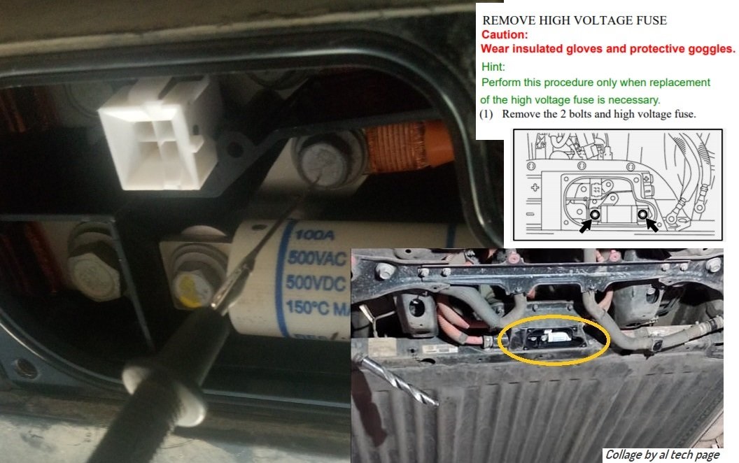
The fuses that are installed in the battery junction box under the car are Farraz Shawmut A50QS50-4 fuses and each of the ones that I’ve come across has a handwritten resistance on it that is in the neighborhood of 1-2 milliohms. The three A50P50-4 fuses that I received had no resistance rating on the fuses themselves and I couldn’t find one in the specs sheet but I measured one at 0.2 Ohms, one at 0.1 Ohms and one at 0 Ohms which just means that it was below what my multimeter could measure. So pretend that they have a typical resistance of 0.1 Ohms. When charging at full speed, 40 Amps RMS are being transmitted through them so V=IR=40 Amps * 0.1 Ohms and 4 Volts are dropping across the fuses. P=IV=40 Amps * 4 Volts = 160 Watts (!) being dissipated… per fuse. And the two fuses are next to each other. In a plastic case buried in a metal case. This is a large fraction of the total inefficiency of the charging system and, at the very least, would be worth a redesign for that reason alone. But even with liquid cooling of the charging system, I could easily see the fuses developing sufficient heat to exceed their 150 C rating and failing over time.
So, the simple fix should be to replace the A50P50-4 fuses with A50QS50-4 fuses, which have identical current, voltage and temperature specifications, but those fuses are too large to fit in the charger. Well, the two problems have the same solution and if I had known about this issue earlier I would have had a retrofit part waiting. The solution is to run wires through the wall of the charger, out to an external fuse box which is sized for the larger fuses. If you wanted to, you could install the stock A50P50-4 fuses and just parallel the wires to the fuse box but leave the A50QS50-4 fuses out of the box until you had a failure. You could diagnose the failure by using the fuse box as a test point and, if a fuse read bad, then just install the A50QS50-4 fuse and be back on the road. I credit Jfletter for this idea.
Well, what do you think? Are my calculations correct? Is my solution correct? Is anyone interested in this modification if I get it working?
-Davio
")