I admit that I am not following everything you're saying.
You first show an analog ohmmeter, but later mention a digital one . . . you're using two different test instruments? Note that the TSB specifically calls for using a DVOM (DMM). You can use an analog VOM, but you should know how to use it, and you have to translate Toyota's instructions for a DVOM to a VOM. They do similar things but in different ways.
Using the analog GB instrument, and testing the harness connector: note that the polarity of your test leads
does matter here (see red boxed instructions below):
View attachment 107
Having said that, and assuming your leads were probing the harness connector using the correct polarity, you're correct: with the instrument's selector at x1K and a needle reading of ~20, that's 20k ohms, and your heater passes the test: OK.
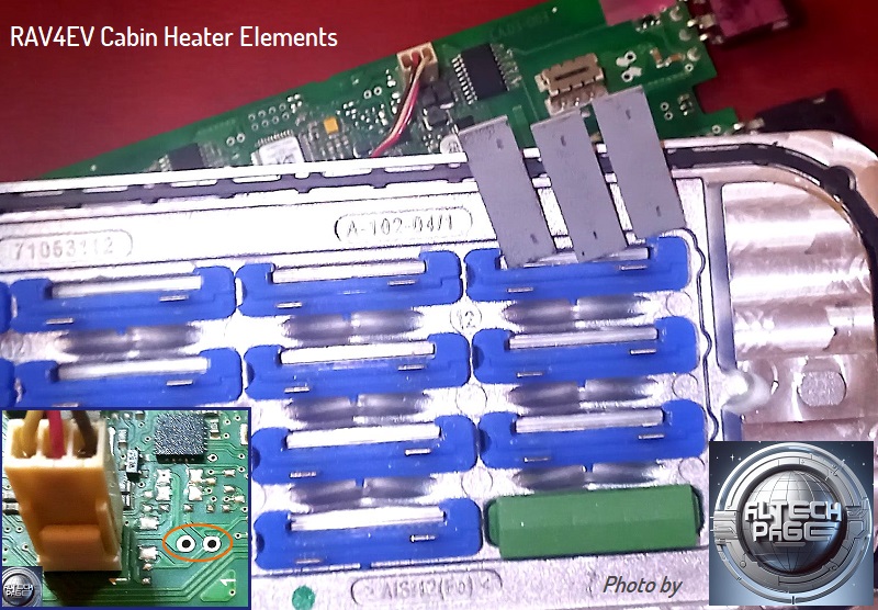
Next, the Cabin Heater fuse inside the DC-DC Converter test:
View attachment 108
For this test, use the audible continuity setting of your GB analog meter:
View attachment 109
Polarity of test leads is
not important for this test.
Probe the indicated terminals on the DC-DC Converter for continuity.
View attachment 110
Note that the TSB
shows but does not
state that the HV lead is unbolted during testing (probe the boss that the HV lead bolts to, not the HV lead itself). I don't know if there's a difference that your analog instrument would pick up, but I point this out in case someone else, using a DMM, gets a weird reading (ie >0>infinity), which could happen with a bad fuse AND the HV lead still connected. In your case, I assume a blown Cabin Heater fuse inside the DC-DC Converter, testing with lead on or lead off, both would read well above zero (continuity), which is good enough to condemn the fuse.
Simplifying: if you obtain any reading higher than zero on your GB analog instrument, the fuse is bad.
---
"Infinity" (open circuit) on your GB meter is on the left side of the scale, not to the right of zero:
View attachment 111
That's the equivalent of "OL" on a typical DMM, or Toyota's "(O/L)" in their TSB.
HTH


")